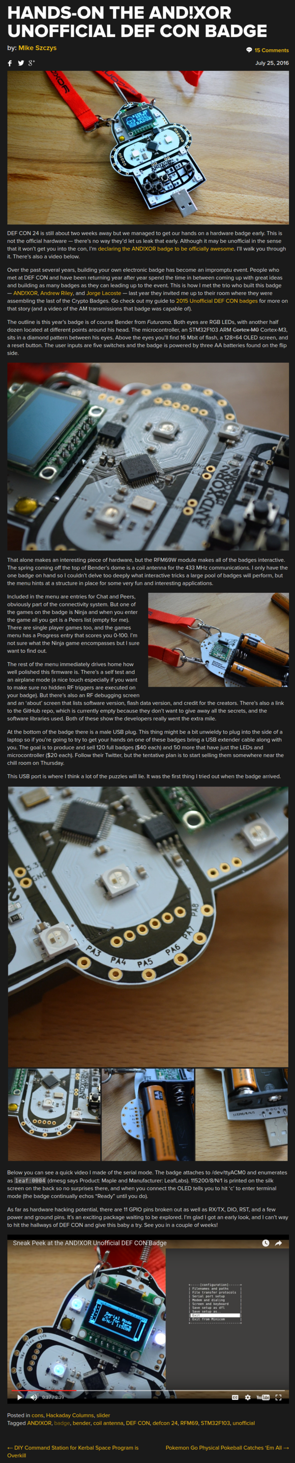
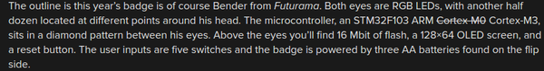
- Above is the AND!XOR badge.
- It has a shape of that Futurama robot, Bender.
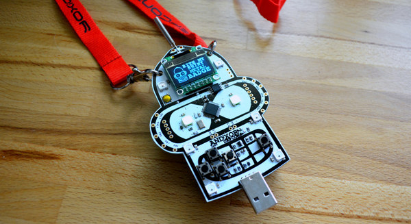
- There are some GPIO pins.
- This badge can also be used as a micro controller.
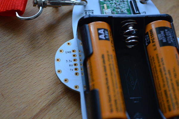
- There are ground and voltage pins and RX and TX pins for serial communications.
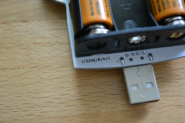
- There is normal USB male connector in the bottom of the badge.
- You can connect this into computer and do serial communications.
- The good thing is that this badge can be used in serial communication.
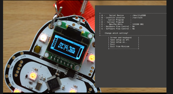
- Here is an example video on how to edit this badge setting via Serial communication, https://www.youtube.com/watch?v=OgD4Es2KB5g.
- This is actually good for my project. So, I only to create the Python codes to alter the functionalities of my badge.

- Specifications.
- 1 USB port.
- 128x64 OLED screen (can be also those classic Nokia screen).
- 16 Mbit of Flash memory.
- 3 AA battery slots.
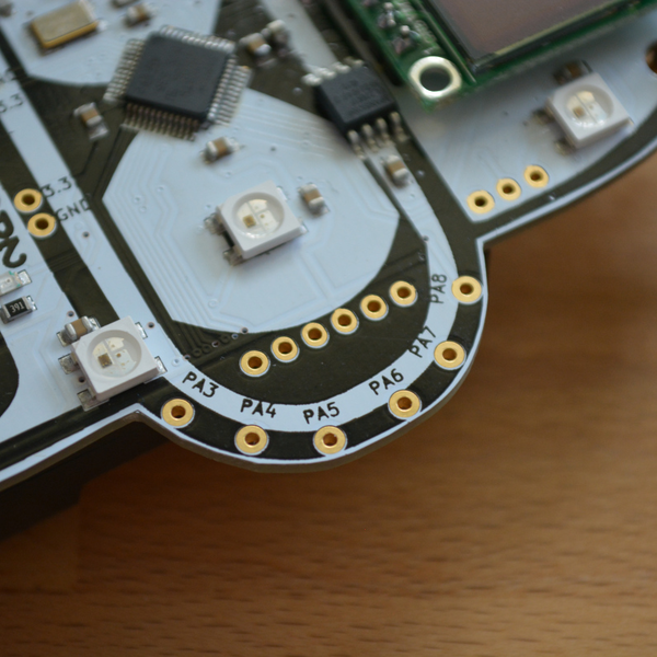
- 5 switches.
- Power pins.
- RFM69W for 433 MHz communications.
- RGB LEDs.
- Serial pins.
- Several GPIO pins.
- STM32F103 ARM Cortex - M3.
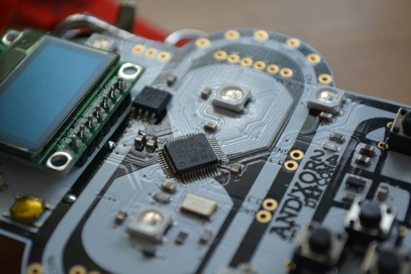
- Above is the image of the STM32F103 ARM Cortex - M3 controller.
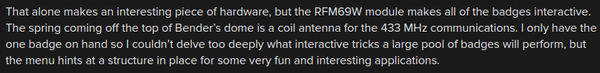

- This badge has a RFM69W for 433 MHz communications.
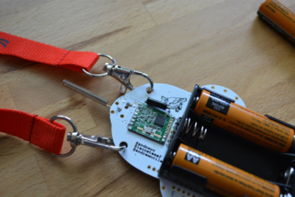
- Above is the images of the badge's antenna.
- The green PCB is the RFM69W.
- The firmware for this badge is quite polished.
- There are a self test and an airplane mode.
- The airplane mode is to make the user sure that there are no unwanted RF communication to the badge.

- The price for full badge is 40 US Dollars.
- The price for just LEDs and micro controller is 20 US Dollars.
- All in all what I like from this badge is that this badge offer a setting interface via serial communications.
- I think I could implement that in my badge.
- Here is the link to the article, https://hackaday.com/2016/07/25/hands-on-the-andxor-unofficial-def-con-badge/.
- Here is the full screenshot of the article.